Katie-J´s refit

V berth cabinetry
stb side
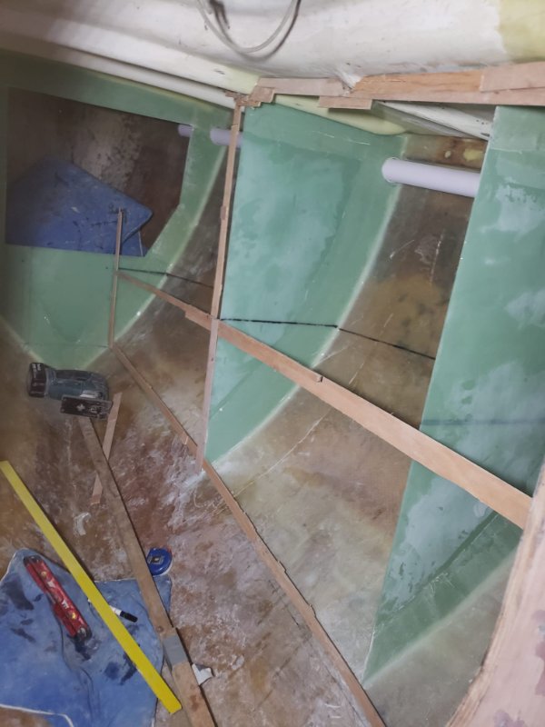
note the PVC pipe which will act as ducting for power, signal and water lines
pvc pipe fitted.jpeg

patterning for fore aft wall.jpeg

rough fit and drawing the openings.jpeg

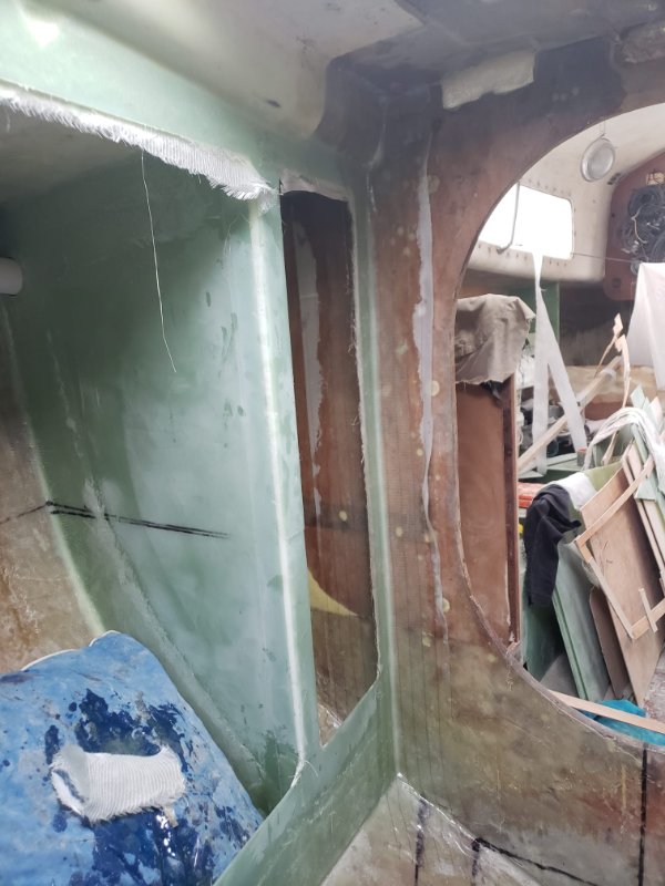
reinforcemen lams.jpeg


stb side fwd locker
locker lid arrangement.jpeg


floor piece
in the end i ended up prioritizing confort over small storage unit. i think its better to have the tallest headroom possible in a place fit for a hobbit to start with
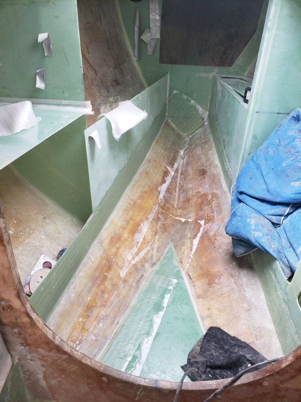
wall and floor lams.jpeg


port side
tabbing fore aft port wall.jpeg

storage port side wall.jpeg
 
galley cabinetry

box mould.jpeg

box mould.jpeg

hacks.jpeg

storage lamination.jpeg

laminating the moulds.jpeg

before cutting the opening.jpeg

the idea works!!.jpeg


final position on the boat (the wall wasnt given the storage, this was a prior rough fit)
galley view.jpeg
 

Attachments

  • box demoulded and trimmied.jpeg
    box demoulded and trimmied.jpeg
    169.4 KB · Views: 256
new cockpit lockers
this model despite its cruising capabilities (which are great by the way for the boat it is) was designed as a daysailer, weekender at most, so storage aint something the original design pays attention to.
the cockpit is yet another area where space needs to be created to properly house equipment
port locker lid before.jpeg

port locker lid after.jpeg

cutting the sheet locker lid.jpeg

sheet locker open.jpeg

this will be a sheet locker built on the frame of the cockpit locker itself, it will self drain to the cockpit once finished.

leaving it ti cure.jpeg

both cockpit locker lids
 
in my quest to maximize storage and ergonomics i decided i needed to lower the cockpit floor. i will build a rigid bimini and ideally i want to have standing head room. at 5' 7" its not that difficult to achieve.
so i had to cut the whole cockpit floor piece
before cutting the floor piece.jpeg
after cutting the cockpit floor.jpeg

cockpit floor before grinding.jpeg
cockpit floor after grinding.jpeg


this was a rough fit at 70mm below the original height. this ended up to be number i was looking for as it always enable me to keep tha majority of the under cockpit unclaimed space.
dry fit at 70 mm outside.jpeg
dry fit at 70 mm in.jpeg


templating the partitions for the under cockpit storage lockers
templating transfering cockpit lockers partitions.jpeg

dry fit partitions.jpeg

not the 2 side dray channels, laminated from an oval shape, created by taping 2 pvc pipes, 2 inch diameter and then cut to a J profile shape
profile for new drain.jpeg


after curring the hatches.jpeg

cockpit lockers seen from aft.jpeg
 
solid dodger build
to build it i first needed to peel the whole cabin top
before peeling.jpeg

half way peeling.jpeg

fully peeled.jpeg


trying to have a first feel for the volume and shape involved in the making of the dodger
mocking up dodger 2.jpeg

mocking up dodger 3.jpeg


very first anchoring laminations
dodger main acnhor points 2.jpeg

dodger main acnhor points.jpeg


another step towards the intended shape
gaff tape.jpeg

fully gaffed.jpeg


laminating a couple of biax layers to have some structure to it
peelply removed.jpeg


demoulded
demoulded.jpeg


refitted
refitted.jpeg


fairing it and applying peel ply to iron out the surface
peelply fairing.jpeg

texture 2.jpeg


and thats it guys, the is pretty much where i am presently
nexts steps are to sand the fairing down, tune it some more, laminate from the inside, fair, sand and tune the inside, then strip plank with G10 strips, and laminate until im happy with its strenght, when it doubt laminate some more!
the cloth im using it biax, 400 gr/m2, 45/45 angle. im also going to use some CSM to help getting some meat on.
 
A question about structural materials.

i will be replacing the original rudder post with a wound filament fibreglass tube. the original tube was made of steel, glassed at both ends, thus avoiding water ingress and packing nuts ( proven and simple arrangement in my view), the new tube will a fraction of it, glassed only to the bottom, but very robustly reinforced with G10 collars and biax cloth, meaning i will have to install a packing gland/nut.
my gut tells me to go at least 12mm (1/2 inch) on the wall thickness

for the bearings i will use a, machined, free spinning, vesconite, or delrin like polymer (something that doesnt absorb water in the long term) for both the bottom (always immersed in water) and top, near the tiller head.

it would be great hearing from the forum's fibreglass experts about the minimum desired wall thickness of said tube.

The original rudder shaft was 57 mm OD, i will be increasing it to 60mm or the next upper number being usually manufactured (to make for an easy future replacing situation)

thanks for any info
 
Last edited:
scribbling lines
getting the window scribbled 2.jpeg
getting the window scribbled.jpeg


before cutting
before cutting 2.jpeg


after cutting (from several viewpoints)
window cut portside.jpeg
window cut stern.jpeg
window cut. bow.jpeg
window cut.jpeg


uglies to fix (wavy sections)
uglies to fix.jpeg


problems with compound curves
gaps created by twisting over 2 axis upon a short distance.
im going to patch the gaps as you would patch thru hulls, get the overall shape (a bit oversized for a later trim), and slap layers of cloth together, tightly cinged then use thickneed epoxy to bed and bridge the remaining mm
problems with compound curves 2.jpeg
problems with compound curves.jpeg
 
got around to continue to refit

main bulkhead works

before filling some cavities
main bullkhead before filling voids.jpeg


after
filling the voids with G10 pieces.jpeg


laminating central and portside sections
laminating the centre of main bulkhead.jpeg


port side mainbulkhead reinforcing.jpeg


in the mean time i also received the SS metal pieces i had designed as the reinforcement pieces to counter the mast´s compression force.
its all 6 mm SS , polished in the visible side
there is a visible slant on the fwd piece, and also in the aft one, but its quite noticeable in the fwd one. im not going to fix it.
just going to bridge the gaps with G10 sheets, cloth and thickneed epoxy, which, by squeezing out will make for a flat surfaces, making both surfaces match

aft metal piece.jpeg


fwd metal piece note the slanting towards port side.jpeg
 
integral water tank works

got some pvc pipe to route the cabling from the batteries to the windlass, and to the main switch board.
i think its a good solution, makes for shorter runs and also hides the cabling

dry fit and after hole sawing the hole
hole drilled for pvc pipe.jpeg


after glassing it in.
had 3 layers of cloth glassed so far but im going for more. dont want this thing coming apart, having water all over the place and worst: having to build it again!

electric acess pipe glassed in.jpeg


glassed some lips where the top lid will be set upon
everything is filleted and then 2 layers of biax cloth. might be overkill but i try to make stuff that would be load bearing in case a heavy load was dropped (me falling into it for instance)
filleting the lid supporting lips in place.jpeg


glassed the aft wall and the inside of the longitudinal wall
laminating aft wall water tank.jpeg


laminating inside wall water tank.jpeg
 
cockpit floor works

gor started on making the lids for the openings i cut out previsouly
cut some strips with a grinder and put everything together with tape, filleted and glass over it

gaf tape G10 pieces in situ.jpeg


starting the new lids of the cockpit floor.jpeg
 
other laminations

laminated both bunks to the hull (only STB is depicted)

another vire stb bunk lamination.jpeg


another view from stb bunk lam. note the "shield" piece installed to make the bunk watertight and create space on the inside to install/remove the transducer
laminating stb bunk storage woth shield install.jpeg


V berth cabinetry reinforcements
reinforcing port side cabinetry.jpeg
 
some morw work got done in the meantime

i glassed in the under cockpit floor partitions, making ready to reglass the floor in the near future
cockpit floor partitions.jpeg


reinforced the aft water tank wall and centre cockpit lockers walls with a couple of lams
cockpit floor partitions.jpeg


and scribbled the lines for the diesel tank lid
fuel tank lines.jpeg
 

Attachments

  • water tank aft wall and cockpit reinfocments.jpeg
    water tank aft wall and cockpit reinfocments.jpeg
    253.3 KB · Views: 262
got to cut the water tank lids to be glassed in the future also
aft lid
this is after i realized upon templating that a full piece wouldnt be able to fit.
will be glassing a small lip to the underside of the fwd exposed edge to have something for the fwd lid to rest upon.
water tank lid aft.jpeg


both lids on
both lids.jpeg
 
cockpit floor hatches
prepped the floor piece by taping it with pvc tape as a release agent
used the original cutout pieces, cut the cloth strips and laminated it along the edges. applied a bead of thickened epoxy just before the cloth so it would fill cavities and help rounding the corners
before demoulding.jpeg


small lid demoulded
you can see the excess thickened epoxy coming out, pretty easy to chisel out and finger sand
i will laminate more layers to beef it up, this was just to gain a stable surface for that
demoulding cockpit floor small lid.jpeg


big lid
big cockpit floor lid.jpeg
 
building the port and centre B berth lockers

decided to make it in one single piece. and this time it actually worked without incidents
templating port center locker.jpeg


transfered the shape onto 3mm G10
bit of waste there, but thats life
trasnferign to G10.jpeg


final shape
lid cut.jpeg


so i took this to the boat, dry fitted and imposed the composting toilet footprint on it, (in its stored position) (thats the plywwod shape you see) to have a feel for the space available.
composting toilet in.jpeg


it became apparent i could take storage "real estate" fwd of the toilet.
which meant a extra partition was need to separate them.
templating
templating partition.jpeg


Cut G10 piece
fwd partition.jpeg


a view on the storage size. pretty decent.
fwd storage unit.jpeg


"final" look with the lids cut out
port and center locker.jpeg
 
Forum posts represent the experience, opinion, and view of individual users. Boat Design Net does not necessarily endorse nor share the view of each individual post.
When making any potentially dangerous or financial decision, always employ and consult appropriate professionals. Your circumstances or experience may be different.

  • Back
    Top