Doug Lord
Flight Ready
- Joined
- May 26, 2009
- Posts
- 16,679
- Reaction score
- 354
- Location
- Cocoa, Florida
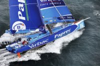
Dinghy Design: Open 60 influence? T2 curved foils
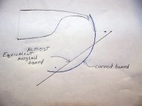
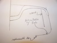
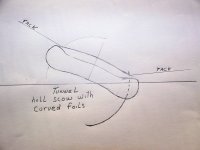
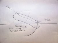
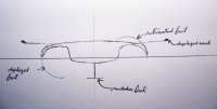
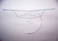
Below right is a rough sketch that shows a straight ,angled board compared to the curved foil being designed specifically for the T2 application. The angled foil(45 degrees) requires more area to develop the same or close to the same vertical lift* but it also requires the boat structure to be 3 feet wider and when retracted on both sides the beam of the boat increases 8'(!). When fully down the straight angled foil draws 8" more than the curved foil.
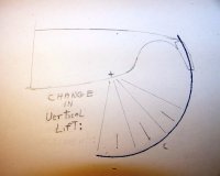
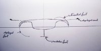
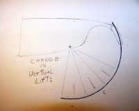
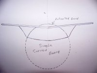
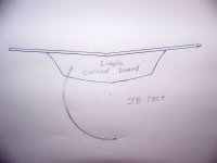
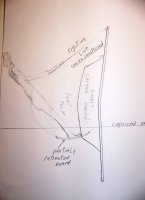
The angled foil will always be developing some vertical lift even when you don't want it no matter how much it is retracted-the ratio is always 50% lateral resistance-50% vertical lift. As you may be able to see on the "segmented" curved foil sketch, the curved foil can be retracted for light air, non- "foil assist" conditions to the point where approximately 90 % of the foil area is used just for lateral resistance, not lift. Additionally the lift profile of the curved foil is infinitely adjustable in small increments which is impossible with the straight angled foil. Note that what is adjusted, with the first 40% or so retraction of the curved foil from max deployment, is vertical lift-little to no lateral resistance is reduced as the foil is initially retracted. This incremental adjustability of vertical lift is one of the major advantages of the T2 specific curved foils.
The curved foil does not add any beam to the boat when retracted and could probably be trailered with the boards retracted.
Curved foils offer quite a bit of design latitude in tailoring them to a specific application. The T2 foils are matched to the characteristics of the boat allowing a range of adjustment from max lateral resistance- no vertical lift to max vertical lift and max lateral resistance. The boards will be able to be deployed for the specific conditions in a way that maximises their lift/drag ratio and improves the overall lift drag ratio of the boat.
--
The T2 has a unique design-not seen in any other dinghy anywhere- as best I can tell-that tailors the design specifically for the curved foils with enough beam to allow the foils to generate righting moment in addition to lateral resistance and vertical lift. This results in a unique hull shape suitable for adaptation as a "performance daysailer" or in a modified version as strictly a high performance dinghy. Because the foils develop vertical lift outboard of the hull CB(displacement or dynamic) they also add substantially to the Righting Moment(RM) of the boat increasing the power to carry sail significantly over a boat not having a design capable of maximising the use of the curved foils.
* Note the flatish area on the curved foil when fully deployed. It takes twice that area for the angled foil to even be comparable to the fully deployed curved foil. In addition, the angled foil is shown at 45 degrees because that is the best compromise between vertical lift and lateral resistance. Both the curved foil and the angled foil could conceivably be pivoted about a fore and aft axis so that the head of the foil can move inboard or outboard. That is probably not necessary on the curved foil since the lift profile can be varied so easily by incremental retraction from the max deployed position. Pivoting the angled foil to gain what can be gained in a normal T2 specific curved foil installation would be complicated and even then would still not be very satisfactory.
Pictures: left-segmented lift of curved foil. right- comparison of curved foil to straight angled foil.