Self-righting Vessel Engine Room Ventilation

Matt Cherry

Junior Member
Joined
Dec 10, 2021
Posts
5
Reaction score
1
Location
Southampton
Hi,

I am currently designing a lifeboat which will be self righting.

I'd appreciate any comments or ideas on how to design the engine room ventilation for the vessel.

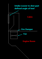
In principle, the design I had come up with so far was (see attached):

A compartment in the cabin space with a louver to become water tight once the vessel is in a self righting manoeuvre (to prevent water entering), with a water trap inside. A fire damper connecting the compartment to the engine room.
The air outlet would be the same design but have an axial fan beneath the fire damper to force air out of the engine room.

The waterline rests quite high, so the intake must be in the cabin space.

Thank you :)
 

Attachments

  • Lifeboat ER Vent.png
    Lifeboat ER Vent.png
    13.3 KB · Views: 644
The waterline rests quite high, so the intake must be in the cabin space.
I assume you mean the intake structure will intrude into the cabin space, not the air intake will take air from the cabin space.
 
Is this a student project? Have you looked at RNLI boats to see the arrangements they use?
 
Is this a student project? Have you looked at RNLI boats to see the arrangements they use?

Commercial.

I have tried speaking with them but struggled to find a contact that was willing to help :(
 
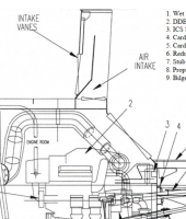
I found the 47ft Motor lifeboat operators handbook for the USCG vessel, but it's very light on detail. I've modelled the design similar to what I can see on the vessel but no information on the intake vanes.

From what I can see on this design though. It appears they have some sort of closing mechanism above the intake louvers which must fall to prevent ingress of water during self-righting.
 

Attachments

  • Lifeboat ER Vent 2.png
    Lifeboat ER Vent 2.png
    205.2 KB · Views: 734
Last edited:
I can remember seeing an arrangement in a book or magazine years ago, I'll try to describe it:
A vertical duct comes down into the engine room on the port side, turns through a right angle and crosses almost to the starboard side of the engine room at its highest point. Same on the other side, another duct comes down, turns a right angle and finishes high up in the engine room on the port side. If the boat rolls 90 degrees to port the port inlet will fill but its outlet is above the new waterline so no water enters the engine room. Same for rolling the other way, even without valves to prevent water entry. If the boat then rolls upright residual water in the horizontal tube is above the waterline (hopefully) and can be arranged to drain overboard. If the boat turns turtle - I can't remember what happens, I presume you are then relying on the louvres/valves,
 
Commercial.

I have tried speaking with them but struggled to find a contact that was willing to help :(

Hi Matt,
Welcome to the Forum.
I used to work in the RNLI design office many moons ago (I left in 1994) - but I contacted one of my former colleagues (Bob) who only retired fairly recently, and he has forwarded on a link to this thread to another colleague (Marsden, who has just retired at the age of 71) who was involved in the design of the ventilation systems, especially re the capsize aspect. And I am sure that Marsden will revert to me soon about this.

But I can tell you now that the intake ventilators are single stage water separators made by Premaberg, as per the link below :
Single stage air water separators - Premaberg Manufacturing Limited https://premaberg.com/product-overview/single-stage-air-water-separators/

In your section drawing in your first post you show the intake louvre that will shut automatically once the vessel heels a certain amount; the RNLI vessels have weighted flaps / dampers in the vent trunking that close the vent automatically when the vessel capsizes, and then open again as soon as she self rights.
I should hopefully be able to supply you with some more details of these in due course.
 
Last edited:
Hi Matt,
Welcome to the Forum.
I used to work in the RNLI design office many moons ago (I left in 1994) - but I contacted one of my former colleagues (Bob) who only retired fairly recently, and he has forwarded on a link to this thread to another colleague (Marsden, who has just retired at the age of 71) who was involved in the design of the ventilation systems, especially re the capsize aspect. And I am sure that Marsden will revert to me soon about this.

But I can tell you now that the intake ventilators are single stage water separators made by Premaberg, as per the link below :
Single stage air water separators - Premaberg Manufacturing Limited https://premaberg.com/product-overview/single-stage-air-water-separators/

In your section drawing in your first post you show the intake louvre that will shut automatically once the vessel heels a certain amount; the RNLI vessels have weighted flaps / dampers in the vent trunking that close the vent automatically when the vessel capsizes, and then open again as soon as she self rights.
I should hopefully be able to supply you with some more details of these in due course.

Wow, thank you for the warm welcome and great info.

Many thanks for the link too that's really helpful.

I'll await for more detail :)
 
Forum posts represent the experience, opinion, and view of individual users. Boat Design Net does not necessarily endorse nor share the view of each individual post.
When making any potentially dangerous or financial decision, always employ and consult appropriate professionals. Your circumstances or experience may be different.

  • Back
    Top