Paul, on another forum had a question I'm interested in as well:
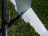
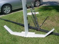
"A quick question- I'm wondering why Moths use such short horizontal (lifting) chords- so short that they must be operating in the sub 500,000 re regime more than some of the time. That regime is notorious for non reattaching flow separation, flow hysterisis in extremus, etc.. It seems the main argument for this might be wetted surface(?), but drag from stressed flow must be an issue for sub 500,000 re chords....
You have the answer correct - reduced wetted surface.
Certainly there are sections that are not suitable for Reynolds numbers under 500,000 - the NACA 6-series being a good example. But there's no problem if the section is designed for it. Many Moths use the H105 section, which was specifically designed to for low-Reynolds number hydrofoils. It's really a matter of section design philosophy.
For example, take the Eppler E817 section. This was designed to be a high-Reynolds number hydrofoil section. It is characterized by rooftop pressure distributions on top and bottom that have a very abrupt start at their design lift coefficients, and concave pressure recoveries, with a sharp transition between the rooftop and the pressure recovery. This approach works for high Reynolds numbers because transition is via amplification of disturbances in the attached boundary layer of the rooftop, and because the high speed means the disturbances (waves, etc.) are small compared to the mean velocity so the foil can stay within its design operating range. Avoiding cavitation is also a high priority.
But these characteristics are troublesome at low Reynolds number where transition occurs via laminar separation bubble and turbulent reattachment. (Below a Reynolds number of 250,000 it's not possible to obtain transition through amplification of the Tollmein-Schlichting waves before reaching the trailing edge because the adverse pressure gradient that would be required would cause laminar separation first.) The abrupt start to a concave pressure recovery results in laminar separation and a long separation bubble, which causes drag. The abrupt start to the rooftop also results in forming a sharp leading edge suction peak at lift coefficients outside the design range. The rapid increase in pressure on the downstream side of the peak can cause laminar separation right from the leading edge that may not reattach at all, leading to a nasty leading edge stall.
To adapt the same section for low Reynolds numbers, the leading edge suction peak is blunted at higher lift coefficients, which results in a more rounded start to the rooftop at the design lift coefficient. The transition between the rooftop and the pressure recovery is smoothed out into a rounded convex shape. This results in a short laminar separation bubble that forms at the aft end of the transition zone at low angles of attack, providing a long run of laminar flow for low drag, and then moves smoothly forward as the angle of attack increases. This ensures the bulk of the pressure recovery is done with a turbulent boundary layer, which is more resistant to separation. This was the approach used in the design of the H105, which had a lot of attention paid to how the laminar separation bubble moves with angle of attack.
There's a lot of controversy over just how much laminar flow is possible in real sailing conditions. Many America's Cup design teams have failed to achieve the amount of laminar flow they'd planned for in the design of bulbs, etc. It may be that bubbles or biological particles in the water get spun up by the shear in the boundary layer, leading to earlier transition than expected from experiments in air. So the effective Reynolds number of a hydrofoil may be higher than the actual Reynolds number. Or the Ncrit lower - say, 3 or even 1.
In general, one can operate a section above its design Reynolds number(s), but one shouldn't use a section much below its minimum design Reynolds number. The key is to design it for a low enough Reynolds number to begin with.