Modelling Stringers - Solidworks

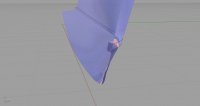
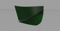
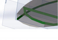
In Rhino, I've done it this way:
- DupEdge (chine)
-OffsetCrvOnSrf (distance of chine log on panel)
-create rectangle for chine log section
-Move and Rotate it to correct position
-Sweep2 (select duplicated edge and offseted curve for rails and rectangle for cross section)
-select maintain height
-Cap
-BooleanSplit (object to split: chine log, splitting object:bottom)
Thats it!

Here's some pictures and the 3dm-files. They were created in FreeSip and imported to rhino as IGES.
 

Attachments

  • 2Aback.jpg
    2Aback.jpg
    311.4 KB · Views: 459
  • 2Afront.jpg
    2Afront.jpg
    188.8 KB · Views: 523
  • 2Bback.jpg
    2Bback.jpg
    266.6 KB · Views: 490
  • 2Bfront.jpg
    2Bfront.jpg
    170.9 KB · Views: 510
  • Sweep_2_A.3dm
    Sweep_2_A.3dm
    130.7 KB · Views: 555
  • Sweep_2_B.3dm
    Sweep_2_B.3dm
    225.7 KB · Views: 550
I have finally cracked the problem (I think). Let me share with you the methods I have developed.

Round Bilge / Stringer:
1. Generate a spline on the surface that represents the centreline of the stringer. Either sketch on the surface or project to surface etc.
2. Split the surface using this spline (probably best to duplicate the surface before doing this).
3. Using the edge of the surface, generate a ruled surface normal to the surface. Set distance equal to the thickness of the stringer.
4. Thicken the ruled surface - set the thickness to the width of the stringer. Thicken equally either side of the ruled surface.
5. Using the hull surface, cut the corners of the stringer protruding outside the hull mold line.

Chine Log: Bit more involved and I hope this makes sense.
1. Offset the hull surfaces either side of the chine inward some nominal distance approx equal to the chine log thickness.
2. Loft a surface between the chine line and the line defined by the intersection of the offset surfaces.
3. Generate a ruled surface normal to the edge of the lofted surface where it intersects the hull line. The distance should be half the width of the chine log.
4. Extend the edge of the rule surface (the edge that intersects the chine line) by half the width of the chine log. You now have a surface with the width of the chine and 'tangent' to the hull at the chine line (by tangent I mean with equal angles between the hull surfaces either side of the chine).
5. Thicken the extended surface inward with distance equal to the thickness of the chine log.
6. Use the hull surfaces to trim away the corners of the chine log that protrude outside the hull mold line.

See the two pictures.

Thanks you all for your help and suggestions. They all helped in one way or another. Now I have just got to figure out how to flatten the hull panels reliably.
 

Attachments

  • Stringer Round Bilge.png
    Stringer Round Bilge.png
    131.6 KB · Views: 617
  • Chine Log.png
    Chine Log.png
    94.8 KB · Views: 618
Well done. There can be other considerations when actually building the stringer(s) or chine stringer(s). Such as, if there is a vertical buoyancy tank side on the inside face ie a vertical (or near) and you do not want a void. By 'void' I mean it could be either side. Also when the stringer is in place it must drain off any sitting water at a nominal hull horizontal position. So a lower chine may require careful pre angling before placing on frames, even if local.

Past experience of building chined and multi chine boats leads me to recommend laminating the chine stringers if more than 10mm thick. Even then, another scenario can occur whereby if you longditudinally cut the stringer on a circular (table) saw for 98% of it's length you can get 7 to 10mm slide over along the length. If you glue up the resulting 'gap' it eliminates significant stress build up.

Nothing to stop one offsetting the saw cuts if say building a 20mm total thickness on inside stringer, prior to shaping for panels. Getting rid of the stress in the stringers does several things. 1. Makes it much easier to achieve desired shape. 2. Allows the ply panels to sit much more accurately once released from the frames, but still held by internal bulkheads. 3. Much easier to plane the panel angles as no stress stops any 'wandering' of the stringer ie you plane it, it gets weaker so bends more - catch 22. On my last multichine boat I only had 5 screws holding it to the frames. On turnover she did not distort even 1mm. You could turn it over, move it around, drop it back on the frames, everything stayed in perfect place. Also saved on a cradling jig, but please note quite extensive structure was built in place whilst upside down, prior to turn over.
 
Forum posts represent the experience, opinion, and view of individual users. Boat Design Net does not necessarily endorse nor share the view of each individual post.
When making any potentially dangerous or financial decision, always employ and consult appropriate professionals. Your circumstances or experience may be different.

  • Back
    Top