Changing dimensions/effect on stability

Don McDermott

Junior Member
Joined
Dec 15, 2024
Posts
8
Reaction score
0
Location
England
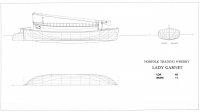
Hello everyone, new member. I've been planning a major wooden sailing boat project for a while, but after struggling for a place to do the build, have just recently redesigned the boat to be somewhat smaller. Originally, I was using the plans of an existing wherry, which is 58'3" length with a 15' beam, but I've altered those plans to 48' with an 11' beam, and also slightly raised the height of the cabinsides, because I'm very tall. The class of boat (trading wherry) is very stable, but some folks are worried that I've impacted the stability and suggested I "ask the experts." I've included two photos, one of the original plans for the wherry Albion, and my new plans, for the wherry Lady Garnet. Any thoughts on how I've altered the dimensions, and how this might impact stability, is greatly appreciated. Thank you!
EDIT: I should add, the boat will be used to carry cargo, and will primarily be sailed on the Thames River. She is not a blue-water vessel, or really even a coastal vessel except very rarely in extremely good conditions.
 

Attachments
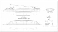
  • HD Albion lines jpeg.jpg
    HD Albion lines jpeg.jpg
    185.5 KB · Views: 321
  • HD Lady Garnet final lines.jpg
    HD Lady Garnet final lines.jpg
    144.1 KB · Views: 352
Last edited:
Stability changes, of course, but nothing can be said for sure. The boat has a length/beam ratio greater than 4, which suggests that if there is a problem, it will not be insurmountable. The type of load you want to carry, the maximum load and its CoG will also have a lot to do with it. If you have any doubts or do not want to take any risks, which seems to me the most sensible thing to do, you should check the stability in the worst loading condition you can foresee.
 
Welcome to the forums.

You have significantly reduced the stability and it should be recalculated.
Length reduced to 0.82 L, however the Beam is reduced to 0.73 B. Since stability scales with the Beam squared and volume, assuming Draft is decreased proportional to length, you have reduced relative stability by 12% and actual stability by 57%.

Xpost with TANSL
Thanks for the reply. I have not changed the hull height at all, not sure how that impacts the actual stability in terms of the formula you use. Since this will be a cargo boat, her draft will depend on how much cargo is in her (probably will carry a max of 20 tonnes). The original boat is very stable, you can have 12 people stand on one side and she won't heel so that you can notice it, and that's without any cargo. I'm aware that my design will decrease stability, but considering how stable the original boat is, I just need to make sure the stability doesn't decrease by a huge amount. Slightly less stable is not a problem.
 
Interesting boats. I can't claim to qualify to comment on scaling a design. The hull form reminds me of the Chesapeake Bay Bugeyes which had similar lines, but usually with finer ends and entirely different construction. Coronet is about as close to the Lady Garnet as I can find in the appendix of the log canoe book. At first glance, they look very different because of the bugeye's schooner rig and bowsprits but the hull form is similar. This is not to suggest altering the design. If anything it would be to consider that possibility that the wherry might have been an ancestor of the bugeye. Wherrys on this side of the pond are small, fast rowing craft similar only in that they are boats.As for the comment on stability, if the hull height is the same and the beam is narrower, well, not for me to say.

The wherrys appear to have more depth to the keel, while the bugeyes have a centerboard since the Chesapeake is fairly shallow. I think that you would find the book in the link interesting because it has the lines for a number of bugeyes that you can compare to the wherry. It might worry me that the Albion sank so many times, but without knowing the circumstances, well, as you said, they are intended for protected waters.
 
Thanks for the reply. I have not changed the hull height at all, not sure how that impacts the actual stability in terms of the formula you use.

Not changing the depth of the hull while narrowing the shown hull form will make the initial stability worse than my figures, especially as you have raised the CG. Initial stability is dependent on GM which is CB+BM-CG. BM is Iwp/volume. Since you kept the same depth of hull you made CB lower (due to the flat floors and large bilge turn) by disproportionally narrowing the hull, and therefore decreased Iwp significantly faster than you changed the volume. So a disproportionately smaller (CB+BM) also while increasing CG means that you have reduced GM well in excess of a simple scaling down.

The original boat is very stable, you can have 12 people stand on one side and she won't heel so that you can notice it, and that's without any cargo. I'm aware that my design will decrease stability, but considering how stable the original boat is, I just need to make sure the stability doesn't decrease by a huge amount. Slightly less stable is not a problem.

Now initial stability and actual stability are two different things, but by reducing the displacement by 40% you have reduced the actual stability by a minimum of 40%...so those 12 guys on the rail is now down to 7.2. Furthermore you proportionally decreased Iwp by 47% so now we are down to 3.4 guys on the rail, a 72% reduction in your measure of stability...this is not "...Slightly less stable..." Really, since you seem to have the weights and lines, it's probably 3-4 hours work for an amature to work up the GM and and the moment to heel to put the rail in the water. There are many texts that will lead you through this process.
 
Thanks for the reply. I have not changed the hull height at all, not sure how that impacts the actual stability in terms of the formula you use. Since this will be a cargo boat, her draft will depend on how much cargo is in her (probably will carry a max of 20 tonnes). The original boat is very stable, you can have 12 people stand on one side and she won't heel so that you can notice it, and that's without any cargo. I'm aware that my design will decrease stability, but considering how stable the original boat is, I just need to make sure the stability doesn't decrease by a huge amount. Slightly less stable is not a problem.
This is really interesting work you're doing! jehardimant is absolutely right. However, I would be careful about using the phrase "slightly less stable." Stability doesn't scale linearly with beam, and the reduction you've made is significant. It might be helpful to do some calculations to quantify the change. If you'd like, send me a private message – I work with stability calculations at a shipyard and would be happy to help.

Thanks for sharing this amazing project!
 
Not changing the depth of the hull while narrowing the shown hull form will make the initial stability worse than my figures, especially as you have raised the CG. Initial stability is dependent on GM which is CB+BM-CG. BM is Iwp/volume. Since you kept the same depth of hull you made CB lower (due to the flat floors and large bilge turn) by disproportionally narrowing the hull, and therefore decreased Iwp significantly faster than you changed the volume. So a disproportionately smaller (CB+BM) also while increasing CG means that you have reduced GM well in excess of a simple scaling down.


Now initial stability and actual stability are two different things, but by reducing the displacement by 40% you have reduced the actual stability by a minimum of 40%...so those 12 guys on the rail is now down to 7.2. Furthermore you proportionally decreased Iwp by 47% so now we are down to 3.4 guys on the rail, a 72% reduction in your measure of stability...this is not "...Slightly less stable..." Really, since you seem to have the weights and lines, it's probably 3-4 hours work for an amature to work up the GM and and the moment to heel to put the rail in the water. There are many texts that will lead you through this process.

Thanks for all this, I will look online for some instructions as you suggest. Greatly appreciated.
 
This is really interesting work you're doing! jehardimant is absolutely right. However, I would be careful about using the phrase "slightly less stable." Stability doesn't scale linearly with beam, and the reduction you've made is significant. It might be helpful to do some calculations to quantify the change. If you'd like, send me a private message – I work with stability calculations at a shipyard and would be happy to help.

Thanks for sharing this amazing project!

Thank you. I've only just joined the forum and I don't think I'm allowed to private message yet, at any rate I can't find the option to PM you anywhere!
 
Thank you. I've only just joined the forum and I don't think I'm allowed to private message yet, at any rate I can't find the option to PM you anywhere!
Kindly find me trhough this e-mail: nikopol90@pm.me

With a hydrostatics and a center of gravity, is possible to have a very good feeling where is your ship regarding stability. Specially if you have a reference ship.

Best regards.
 
Those boats were expected to be loaded with cargo. When empty they commonly added stones as ballast. The type of cargo will change the CG. In the Thames, you shouldn't expect more than a chop, maybe 2 feet or so. However, a poorly loaded ship can easily capsize since the weight of the cargo may be more than that of the ship..
 
There was a thread on scaling and ballast calculations in 2014. It might be interesting to compare the factors in the spreadsheet attached to that post to your scaled design. Using that spreadsheet, the new beam would be 13 feet. No advice, just information.

I looked at the equations to see what the scale factors looked like some years ago. The equations are unnecessarily complex as written. That seems to be the consequence of using Excel to set up a problem where a pencil and paper would have saved a lot of time. We don't always benefit from labor saving devices. Once you work out the math, Excel crunches numbers nicely.

Beam: (C9/($C$7^0.7)*($E$7^0.7)) reduces to C9/($E$7/$C$7)^0.7

($C$7/$E$7) is the scale factor (new length) / (old length). Call it F

=C9/($C$7/$E$7)^0.7 ==> C9/F^.07
(scaled down beam = original beam/F^0.7)

48/58 = F = 1.21
F^0.7 = 1.14
New beam = 15/1.14 = 13.14

This is the best representation of the equations in the spreadsheet that I can do without tabs. All of the C values and E7 are inputs, the rest of the Es are calculated using the equations to the right.
_____________________Input ___Output
Length_________________C7 ____ E7
Sail area ________________C8 ____ E8 = (C8/($C$7^1.85)*($E$7^1.85))
Beam _________________ C9 ____ E9 = (C9/($C$7^0.7)*($E$7^0.7))
Depth _________________ C10 ____ E10 = (C10/($C$7^0.7)*($E$7^0.7))
Freeboard ______________ C11 ____ E11 = (C11/($C$7^0.7)*($E$7^0.7))
Mast height _____________ C12 ____ E12 = (C12/($C$7^1.4)*($E$7^1.4))
Sectional area ____________C13 ____ E13 = (C13/($C$7^1.4)*($E$7^1.4))
Wetted area _____________C14 ____ E14 = (C14/($C$7^1.7)*($E$7^1.7))
Lateral area hull __________ C15 ____ E15 = (C15/($C$7^1.7)*($E$7^1.7))
Lateral area keel __________C16 ____ E16 = (C16/($C$7^1.4)*($E$7^1.4))
Volume hull _____________ C17 ____ E17 = (C17/($C$7^2.4)*($E$7^2.4))
Volume keel _____________ C1 ____ E18 = C18/($C$7^2.1)*($E$7^2.1)
Displacement tot __________C19 ____ E19 = (C19/($C$7^2.38)*($E$7^2.38))
Wetted area tot ___________ C20 ____ E20 = (C20/($C$7^1.63)*($E$7^1.63))
Sail area / wetted area _______C21 ____ E21 = (C21/($C$7^0.22)*($E$7^0.22))
Sail area / displacement tot ___ C22 ____ E22 = (C22/($C$7^0.26)*($E$7^0.26))
 
Last edited:
Forum posts represent the experience, opinion, and view of individual users. Boat Design Net does not necessarily endorse nor share the view of each individual post.
When making any potentially dangerous or financial decision, always employ and consult appropriate professionals. Your circumstances or experience may be different.

  • Back
    Top