BG_Geno
Senior Member
Rick--
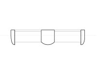
Pictured is (in my opinion) our best bet. Eppler did a lot of work on HYDROFOILS and the 838 has a generous 18.37% max thickness. More importantly for what we are doing, the max thickness is WAY back at 46.5% of the chord. The image is to scale to give you an idea of the shape/size and has a 3mm skin of Carbon Fiber (CF) with a main spar for back to back D tubes.
Keep in mind that for tubes, increasing diameter increases strength exponentially while increasing wall thickness improves strength lineally. You mentioned that the load is distributed evenly, and that is likely the case, however modules of elasticity really don't care. If the "fixed points" are the ends, the loads WILL multiply inwards to towards the center. A perfect example of this in CF are helo main rotor blades. They are fixed on one end and the elasticity (loading) builds out towards the tips.
SW allows you to enter the Modulus of elasticity for your exact CF cloth, weave direction, and resin. Because we only need strength in one direction (the foils very thin and there is no crush loading) the weave choice is pretty clearly dictated.
Now because our blades have to be able to rotate they will be on pins/axles.
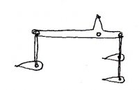
Using your 275 N (60 pounds) loading (is this a bit high maybe?) on a 43" span on the pictured structure I get almost 2" of deflection (about 50mm). Thats actually withing the structural range of the CF with one caveat. With both positive and negative pitch in the wheels rotation your subjecting the blade to that deflection in BOTH direction about 30 times a minute...over and over thousands of times.
You also loose over an inch of your width at the extreme of that flex. That means about a half inch gap at either end and thats going to be draggy as hell.
I think the 2" (50mm) of flex might seem high to you because your seeing the 80mm width in your mind and not the 14mm thickness that isn't even a rectangular cross section...60 pounds in the center of a 1.1m length of something that thin is a LOT. Turn it on it's edge and we get a lot more strength. Even end to end as a column it could likely do it, but on the flat is tough.
Picture a hight tech 1m R/C sail plane CF wing which is essentially what this is. Now picture it with a 60 pound fuselage lol.
Anything over about 25" or so and your just going to be beating the blades to death. Either go shorter, or give me more diameter (much bigger chord) to work with.
Pictured is (in my opinion) our best bet. Eppler did a lot of work on HYDROFOILS and the 838 has a generous 18.37% max thickness. More importantly for what we are doing, the max thickness is WAY back at 46.5% of the chord. The image is to scale to give you an idea of the shape/size and has a 3mm skin of Carbon Fiber (CF) with a main spar for back to back D tubes.
Keep in mind that for tubes, increasing diameter increases strength exponentially while increasing wall thickness improves strength lineally. You mentioned that the load is distributed evenly, and that is likely the case, however modules of elasticity really don't care. If the "fixed points" are the ends, the loads WILL multiply inwards to towards the center. A perfect example of this in CF are helo main rotor blades. They are fixed on one end and the elasticity (loading) builds out towards the tips.
SW allows you to enter the Modulus of elasticity for your exact CF cloth, weave direction, and resin. Because we only need strength in one direction (the foils very thin and there is no crush loading) the weave choice is pretty clearly dictated.
Now because our blades have to be able to rotate they will be on pins/axles.
Using your 275 N (60 pounds) loading (is this a bit high maybe?) on a 43" span on the pictured structure I get almost 2" of deflection (about 50mm). Thats actually withing the structural range of the CF with one caveat. With both positive and negative pitch in the wheels rotation your subjecting the blade to that deflection in BOTH direction about 30 times a minute...over and over thousands of times.
You also loose over an inch of your width at the extreme of that flex. That means about a half inch gap at either end and thats going to be draggy as hell.
I think the 2" (50mm) of flex might seem high to you because your seeing the 80mm width in your mind and not the 14mm thickness that isn't even a rectangular cross section...60 pounds in the center of a 1.1m length of something that thin is a LOT. Turn it on it's edge and we get a lot more strength. Even end to end as a column it could likely do it, but on the flat is tough.
Picture a hight tech 1m R/C sail plane CF wing which is essentially what this is. Now picture it with a 60 pound fuselage lol.
Anything over about 25" or so and your just going to be beating the blades to death. Either go shorter, or give me more diameter (much bigger chord) to work with.