Foiler Design

Terry & Doug,

I'm still here for a while, today.

Here's the definition of dihedral angle for an aircraft that you'll find (in Wikipedia) :" Dihedral angle is the upward angle from horizontal of the wings or tailplane of a fixed-wing aircraft."

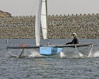
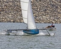
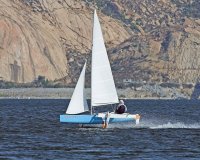
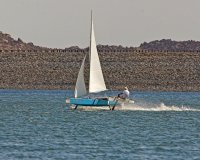
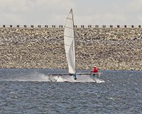
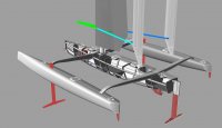
By this definition, I'd say my foils have 60 degrees dihedral. This compares to about 45 degrees (I think) for Hydroptere. I made it so large partly just to get enough foil down low enough to fit the space available & partly as a way to inhibit ventilation. Initially, the foils had 4 fences on each leg of each Vee, but they were clearly causing significant separated areas & I have been much happier with the performance since I removed them.

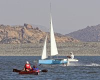
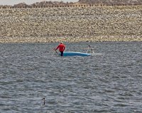
Broomstick first sailed as a conventional trimaran without foils in 2003 & with foils in May, 2004. This is a part-time 1-man effort. I've sailed usually fewer than a dozen times a year since then, so progress is necessarily slow.

Doug Halsey
 
Foiler Design Series-Doug Halsey's Broomstick

This is the fourth in my series presenting the technical details of as many foilers as possible.
So far:
1) Mirabaud post 895
2) Rave post 896
3) Moth post 897
Down the line I hope to convince Jeff to place this info all in one place-perhaps at the begining of this thread-so it will be easy to get to.
--------------------------
Broomstick
--
This boat is a surface piercing foiler designed and built by Doug Halsey and I thank him for his generous contribution of this information.
--LOA 15'
---
--BEAM max 17'
Between tips of "V" foil 13'9"
---
SAIL AREA:
1) 108 ft^2 using the usual rig (main + jib)
2) 143 ft^2 using the larger main + same jib (haven't used since 2007)
---
WEIGHT: ~210 lbs for usual setup (smaller rig, 7' amas, etc.) + crew=355lb
--20 lbs less when I don't use the amas-190lb+crew= 335lb
--20 lbs more when I use the larger rig-230lb+crew= 375lb
--145 lbs = crew weight
---
FOILS: Describing surface-piercing foils is obviously harder than fully-submerged foils, since
the area is constantly changing, but maybe this will make sense:

--Dihedral Angle = 60 Deg.
--Chord = 6"
--Section Shape = Conventional, uncambered, untwisted ~NACA 0012
--Foil Span = 23.3". This is the horizontal projection of the span of 1 foil at takeoff, which I'm
defining as the point where the lowest point of the main hull just touches the water, assuming the boat
is level in both pitch & heel. At higher speeds, the span of the leeward foil reduces to some fraction
of this value, depending on the speed, position of my weight, main-foil incidence setting, aft-foil
incidence, etc. Span of the windward foil reduces much more, sometimes almost to 0.
--Foil Area = 23.3" X 6"= 139.8 In^2 = .97 Ft^2 (Again at takeoff-each side)
--Main-Foil Incidence : Currently ~8 1/2 Deg. with respect to the design waterline. This has been changed a few times over the years, each change requiring patching & redrilling bolt holes in the foil brackets (attached to the crossbeam) & the vertical stubs (at the top of each foil). Too small an angle gives insufficient righting moment when hullborne. Too large an angle gives too much bow-down pitch angle when flying.

--Note:I've designed a new set of main foils, with similar planform, but cambered & twisted sections. Also a new deeper aft foil. It will probably be several more months before I sail on foils again though.
---
AFT-FOIL INCIDENCE : This angle is adjusted with a screw mechanism & control bar under the tiller. In
past years, I would have to luff up, lean over the aft deck & go thru all sorts of contortions to adjust
it, so it was usually set at some sort of compromise angle. Last year, I improved it so that I can
adjust it (on 1 tack anyway) by twisting the tiller extension. That way I could try to find the
"optimum" setting where the boat flies at just the right height for the existing conditions.
---
Construction
--Main Hull- planked foam, epoxy glassed
--Ama-stich and glue/ 3mm Okume ply
--Foils- wood,hand shaped and epoxy glasse

More info here(scroll to near bottom): http://www.foils.org/gallery/sail.htm Since that time there have been several improvements & speeds over 25 knots have been recorded on 3 separate occasions.
==========
Pictures below by Terry Curtiss:
 

Attachments

  • Doug Halseys foiler wo amas-from Multihulls on boatdesign.net.jpg
    Doug Halseys foiler wo amas-from Multihulls on boatdesign.net.jpg
    121 KB · Views: 1,098
  • Broomstick_4.jpg
    Broomstick_4.jpg
    717.3 KB · Views: 1,012
  • Broomstick_5-.jpg
    Broomstick_5-.jpg
    565.9 KB · Views: 963
  • Broomstick_6.jpg
    Broomstick_6.jpg
    306.7 KB · Views: 802
  • Broomstick_8.jpg
    Broomstick_8.jpg
    637.6 KB · Views: 775
  • Broomstick_4-15-09_.jpg
    Broomstick_4-15-09_.jpg
    740 KB · Views: 859
  • Broomstick3.jpg
    Broomstick3.jpg
    812.6 KB · Views: 910
Last edited:
I notice the skip is sitting in a cockpit with no possibility or intention of hiking, so the foils are functioning as Bruce foils - cancelling heeling moment - as much as they are lifting the hull. Bruce foils are usually around 45 deg. I have been also considering that.

It looks much more like the kind of boat that would tolerate beginner's mistakes without a total meltdown, than some of the foilers I have seen on your threads, Doug, and is closer to my idea of what a peoples foiler would look like. Certainly eliminates most of the athleticism from the equation. Sail looks like a land-yacht rig.

The performance-oriented guys will likely crap all over it.
 
Don't know if this has been posted before?
 

Attachments

  • hwx3-1.jpg
    hwx3-1.jpg
    150.8 KB · Views: 1,081
  • hwx3-3.jpg
    hwx3-3.jpg
    58.2 KB · Views: 824
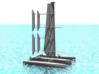
I'm intrigued by the wingsail design and would like more details if anyone has a link ...
 
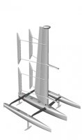
I saw that site sometime earlier but hadn't focussed on the twin control surfaces behind the wingsail. I imagine the control surface has to be offset to one side of the wingsail to get it out of the turbulence, since it is so short-coupled. The short coupling distance also requires a larger area which is addressed by the twin configuration.

The situation is analogous to an aircraft with a short fuselage in which the horizontal stabilizer is offset vertically, typically on top of the vertical stabilizer.

I suspect the reason for 2 control surfaces is the usual human obsession for left-right symmetry. One would not bother for an aircraft since up-down symmetry is not a common feature in Nature so we do not notice its absence. A single control surface offset to either side of the wingsail would work just as well IMHO, although it might look strange.

Since I am interested in trying a wingsail with a "tailplane" sometime, the potential for a turbulence problem is a lesson to be noted and I am glad it came to my attention.

Thanks Doug.
 
...
I suspect the reason for 2 control surfaces is the usual human obsession for left-right symmetry. ...

A rigid wing cannot be luffed or reefed, so it is very important that it be capable of being completely feathered and respond very quickly to gusts. This drives several aspects of the tail design.

Human obsessions aside, there are many reasons for the two control surfaces. One reason is the surfaces can be slightly toed in to eliminate a deadband that can occur at low angles of attack, producing a more linear response for small inputs. This is important when maneuvering the craft at low speed and for keeping the wing completely feathered when needed.

Another reason is to improve the aerodynamic damping. For a given tail volume (area times tail length), aerodynamic damping goes up with the square of the tail length. The length of the tails are limited by practical considerations, such as the need to feather the wing into the wing when docked without the tails sweeping people off the dock. Twin tails reduce the chord, allowing the area to be concentrated closer to the ends of the tails.

Then there are failure modes. The typical failure mode for an electromechanical actuator is to jam in place. With a single tail, this would result in loss of control of the wing, possibly trimmed at high lift with no way to neutralize it. However, with twin control surfaces, the working control surface can always be set to neutralize the failed surface.
 
Interesting points, Tom. You have likely explained the use of multiple control surfaces for that boat.

The deadband and aerodynamic damping problems are unlikely to be of significance on my small sailboat, my boat is not docked so tail length is less limited, and the control surface will be moved manually so there will be no electromechanical actuators failure modes to worry about. I will stay with the single "tailplane" concept for my experiment if it goes ahead, but there's more to it than I thought.
 
Another aspect of the HarborWing design you may not have noticed is the wing is split in half, with the upper and lower wings rotating independently. That's why you see four control surfaces instead of two. The reason for the split wing design is to allow the wing to feather more completely when there is wind shear.

When there is wind shear, the head and foot experience different wind directions, so it's not possible to trim a single wing so that it has zero lift all along the span. If trimmed for zero net lift, there can still be a significant heeling moment. The boat will be buffeted and try to sail when moored. The split wing design allows each half to feather into its own mean wind direction, significantly reducing the impact of wind shear on the boat.

It also allows the wing to be trimmed more efficiently when sailing. Although wing twist, either of the wing itself (ala Cogito) or just the flap (ala USA 17) is a more efficient way of achieving this while sailing than having a discrete change along the span.

Most boats spend more time moored than sailing, and with a rigid wing rig it's important to pay a lot of attention to the behavior of the wing when moored.
 
Good point. There are several thread that raise this point in connection with dynarig sails and wing-sails. Splitting the wing into sections would be an alternative to the flexible wingsail proposals that have been discussed here and there.

I considered using a flexible wing with the control surface close to the head so I could increase the alpha at the foot of the sail with a sheet, but I ran into construction difficulties with that approach. I am still developing concepts to address the issue. It is much more of a problem on a small boat than a large, tall rig that does not have to reach down into the slow wind flow near the surface to develop power.
 
Another aspect of the HarborWing design you may not have noticed is the wing is split in half, with the upper and lower wings rotating independently. That's why you see four control surfaces instead of two. The reason for the split wing design is to allow the wing to feather more completely when there is wind shear.

When there is wind shear, the head and foot experience different wind directions, so it's not possible to trim a single wing so that it has zero lift all along the span. If trimmed for zero net lift, there can still be a significant heeling moment. The boat will be buffeted and try to sail when moored. The split wing design allows each half to feather into its own mean wind direction, significantly reducing the impact of wind shear on the boat.

It also allows the wing to be trimmed more efficiently when sailing. Although wing twist, either of the wing itself (ala Cogito) or just the flap (ala USA 17) is a more efficient way of achieving this while sailing than having a discrete change along the span.

Most boats spend more time moored than sailing, and with a rigid wing rig it's important to pay a lot of attention to the behavior of the wing when moored.

Kind of like this?

http://www.eng.auburn.edu/organizations/AIAA/files/papers/2009/masters/Welstead_2009.pdf

:?:
 
A little bit. But only two segments and tail controlled.
 
Forum posts represent the experience, opinion, and view of individual users. Boat Design Net does not necessarily endorse nor share the view of each individual post.
When making any potentially dangerous or financial decision, always employ and consult appropriate professionals. Your circumstances or experience may be different.

  • Back
    Top