Aluminium mast: crack or scratch?

Pam Hoppenbouwers

Junior Member
Joined
Mar 16, 2024
Posts
5
Reaction score
1
Location
Maastricht
Hej, I would like to have your opinion about this situation.

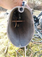
Mast from a 20 year old Farrier F9 tri, rotating mast, length about 13 meter, setup from bottom to top: 1 m unstayed, 4,5 m stayed, spreader, 4,5 m stayed, connection front stay + back stays, 3 m unstayed to top, 5 cm bend over stayed 9 m, thickness aluminium: 3,7 mm

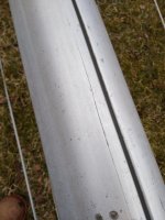
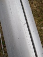
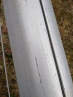
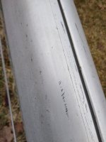
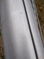
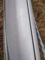
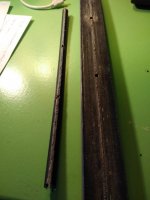
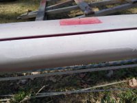
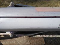
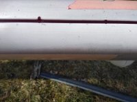
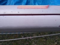
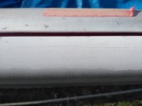
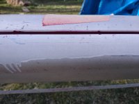
I removed the HMPE sailtrack and cracks?/scratches? now show mostly under it. In the process of making new laminate covered HMPE sailtrack, but not sure or the mast is OK. See pictures
  • the crack/scratch is over most part of the mast, also the upper unstayed part
  • only on one side of the original masttrack, in the corner of
  • on some parts the surface is uneven at the different sides of the crack/ scratch
  • searching on internet I was not able to find any pictures of identical situations
  • I suppose compression and tension loads are more or less equal in aluminium so I can't explain why the backside
  • Mast is not new but looks fine except 1 spot of pitting corrosion (20 mm2)
  • Poured thinner over the crack/ scratch which runs of smoothly. Pushing a paper towel a few cm next to the pouring spot gets wet.
My question: is it a scratch and can I use the mast? Or is it a crack and do I have to find another one?
 

Attachments

  • IMG_20240315_144914774.jpg
    IMG_20240315_144914774.jpg
    200.7 KB · Views: 280
  • IMG_20240316_094814163.jpg
    IMG_20240316_094814163.jpg
    125.8 KB · Views: 293
  • IMG_20240316_094822054.jpg
    IMG_20240316_094822054.jpg
    110.2 KB · Views: 282
  • IMG_20240316_094825523.jpg
    IMG_20240316_094825523.jpg
    104.2 KB · Views: 272
  • IMG_20240316_094835687.jpg
    IMG_20240316_094835687.jpg
    102.1 KB · Views: 274
  • IMG_20240316_094842858.jpg
    IMG_20240316_094842858.jpg
    99.8 KB · Views: 314
  • IMG_20240316_094906419.jpg
    IMG_20240316_094906419.jpg
    128 KB · Views: 288
Last edited:
Hello Pam,
Those look like scratches in the anodized surface rather than cracks in the aluminum mast extrusion to me.
If someone has a better test method please reply.
I am curious how the covered sail track works, do you have a picture of the previous one installed?
 
Hi Tops, thanks for your reply!

The masttrack was from Tides Marine: https://www.tidesmarine.com/product-category/track-slide-systems/. It had severe detoriation on the outside (mechanical and UV). The weak spot is the connection to the inner half round part of it only 3 mm wide. During the past years I drilled/ tapped/ bolted the parts that ripped. The masttrack itself is also quite loose in the mast.
So I decided to build a better version of it. 2 m sections with bolted slugs, HMPE (PE-1000) covered in 1 mm glasfiber. Glued together with 2 component PE glue PE-lijm - S-Polybond PEprofi 50ml https://www.s-polytec.nl/2k-pe-lijm-polyethyleen-klebstoff-spolybond-peprofi.html. Calculated the tension because of differences in thermal expansion coefficient and very well within spec of the polybond.
Now making a mold for glasfiber outside. A friend is making a milling tool for the T mill into the PE. See Pictures
 

Attachments

  • IMG_20240316_121802936.jpg
    IMG_20240316_121802936.jpg
    89.5 KB · Views: 225
  • IMG_20240316_121827234.jpg
    IMG_20240316_121827234.jpg
    98.5 KB · Views: 232
  • Masttrack overzicht.jpg
    Masttrack overzicht.jpg
    49.8 KB · Views: 270
Thanks Pam for the additional information. Do I understand correctly that the mast track and cloth will be glued to the mast?
Nice of your friend to make the tooling. At my work we do a similar operation for seating an o-ring with two passes, first is the access hole and the second is a cutter for the narrow section like these McMaster-Carr https://www.mcmaster.com/products/woodruff-keyseat-cutters/ .
 
Alternatively, you MIGHT be able to use a die penetrant kit. I did not mention this earlier because I considered that a scratch on the mast might capture some of the penetrant and falsely show
the same presentation as a crack.
 
Thanks Barry, I did some reading and realized that I have to change my formulation of the question. So not "scratch or crack" but " how deep is the disturbance and what is happening inside".
Starting asking around for testers. Do you have practical experience with them?
ECT: could show there is an uncommon situation in conductivity, but possibly it is hard to get an objective remaining material thickness measurement from it as current in a cylindrical shape can go all directions so will flatten out the result?
UT: in the examples I see it is used in flat block situations. My situation is a curved outside and a non-flat inside so will give all kind of reflections? Might be possible to use an angled sensor.
Dye method: Can't give an indication about the depth of the disturbance.
 
Do I understand correctly that the mast track and cloth will be glued to the mast?
Originally I wanted to use a slug/bolt system. Maybe I'm a bit old fashioned.. not to trust glue and prefer bolts :). But glue might be not such a bad idea.. taking a part of the load of the aluminium.. would require a bit of extra calculating though.
McMaster cutters: interesting! I saw those kind of cutters while searching for a standard solution. What is your opinion on the best cutter and cutting conditions for PE-1000? height of the T is 3,2 mm, width is 22,4 mm.
 
Originally I wanted to use a slug/bolt system. Maybe I'm a bit old fashioned.. not to trust glue and prefer bolts :). But glue might be not such a bad idea.. taking a part of the load of the aluminium.. would require a bit of extra calculating though.
McMaster cutters: interesting! I saw those kind of cutters while searching for a standard solution. What is your opinion on the best cutter and cutting conditions for PE-1000? height of the T is 3,2 mm, width is 22,4 mm.

I have to ask the machinists for feeds and speeds and cutter selection when I program for them, sorry I cannot answer directly.
https://www.plasticsintl.com/media/wysiwyg/Fabricating_and_Machining_UHMWPE.pdf
The short paper also discusses fastening towards the end.
 
I did some reading and realized that I have to change my formulation of the question. So not "scratch or crack" but " how deep is the disturbance and what is happening inside".
Starting asking around for testers. Do you have practical experience with them?

I was exposed to a flourescent penetrant process once. We manufactured fuel tanks for a customer who wanted the welds tested. We hired a guy to come in and check the couple of tanks.


Fluorescent penetrant inspection - Wikipedia https://en.wikipedia.org/wiki/Fluorescent_penetrant_inspection

Opinions, decisions and observations can be either right, wrong, or remain undetermined. I mention this as I am offering an opinion here and would be the thought process that I would have used to come
to my Opinion that these are surface scratches as compared to cracks that are deeper. Over the years we have repaired quite a few aluminum components that have had cracks.

Picture 1 of the mast cross section. The cross section is extruded and any area of the cross section does not appear to possess an area of stress concentration. Ie an area where I would think that a crack would
occur first. The track corners are pretty much radiused to minimize stress concentrations.

I would suspect that if it is a crack, the line of the crack would be in a relatively straight line along a fatigue line.
Picture 2 and 4, have straight lines near the area of the fillet on the inside of mast where the track profile "attaches" to the main mast. An indicator of a stress concentration here.
BUT
Picture 3, 4, 6 and 7 have scratches that do not lie along this "fault line" and are quite random
Picture 3, 4 and 7, thescratches vary quite far away from the "fault line" and parts are not in line
Picture 6 shows a return inflection point, ie a scratch that does not continue without interuption.
Picture 5 shows quite a few other "abrasion or scuff marks parallel to the scratch, leading me to believe that what ever caused the scuff marks caused the scratch marks.

So for these reasons I am leaning toward the fact that these are scratches not cracks

WRT your new factor, "
how deep is the disturbance and what is happening inside".
The dye penetrant can offer some idea of depth. The process is such that the dye will come back into a second of third layer of the applicated surface and if there is a lot of die on the surface, this die has to have
come from a deeper crack.
 
Last edited:
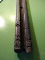
As promised an update. The conclusion: scratch! Thanks all.
 

Attachments

  • M1[1].jpg
    M1[1].jpg
    163.9 KB · Views: 250
  • M2[1].jpg
    M2[1].jpg
    181.5 KB · Views: 251
  • M3[1].jpg
    M3[1].jpg
    172.3 KB · Views: 258
  • M4[1].jpg
    M4[1].jpg
    215.1 KB · Views: 259
  • M5[1].jpg
    M5[1].jpg
    216.2 KB · Views: 240
  • M6[1].jpg
    M6[1].jpg
    184.8 KB · Views: 232
Forum posts represent the experience, opinion, and view of individual users. Boat Design Net does not necessarily endorse nor share the view of each individual post.
When making any potentially dangerous or financial decision, always employ and consult appropriate professionals. Your circumstances or experience may be different.

  • Back
    Top